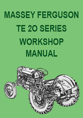
MASSEY FERGUSON TE-20 Series Factory Tractor Workshop Manual | PDF Download

MASSEY FERGUSON TE-20 Series Factory Tractor Workshop Manual | PDF Download
Models covered in this Workshop Manual:
- Massey Ferguson TE-A20
- Massey Ferguson TE-C20
- Massey Ferguson TE-D20
- Massey Ferguson TE-E20
- Massey Ferguson TE-F20
- Massey Ferguson TE-H20
Engines covered in this Workshop Manual:
- 1850cc Petrol
- 2092cc Diesel
Below is a detailed list of topics covered in the Massey Ferguson Workshop Manual:
- Specification
- Specifications for 1850cc Petrol Engine (Clearances, Torque tightening etc.)
- Specifications for Vaporizing Oil Engine (Clearances, Torque tightening etc.)
- Specifications for 2088cc Petrol Engine (Clearances, Torque tightening etc.)
- Specifications for 2092cc Diesel Engine (Clearances, Torque tightening etc.)
- Specifications for Lamp Oil Engine (Clearances, Torque tightening etc.)
- Petrol Engine Rebuild Instructions for TE-A20 and TE-C20
- Lubrication System
- Oil Distribution
- The Oil Pump
- The Oil Filter
- Overhaul of Cylinder Head Assembly
- Camshaft and Timing Mechanism
- Engine Removal and replacement
- Sleeves, Pistons & Connecting Rods
- Diesel Engine Rebuild Instructions for TE-F20
- Introduction
- Lubrication System
- Overhaul of Cylinder head Assembly
- To remove Valve Springs and Collars with Cylinder Head Fitted
- To Dis-assemble and Re-Assemble Rocker and Decompression Shaft Assembly
- Renewing Valve Rocker bushes
- Renewal of Pre-Combustion Chamber Lower Half
- Removing and Replacing Valve Guides
- Valve Seats
- Tappets and Push Rods
- Camshaft and Timing Mechanism
- Cylinder Inserts, Pistons, Connecting Rods and Liners
- Crankshaft and Main bearing Housings
- Cooling System
- Cooling System Petrol Engine
- Cooling System on Vaporizing Oil Engine TE-D20
- Cooling System on Lamp Oil Engine TE-H20
- Cooling System on Diesel Engine TE-F20
- Fuel System
- Petrol Tank
- Tank Mounting
- Remove the Tank
- Function of the Petrol Valve and Sediment Bowl
- Petrol Valve and Sediment Bowl Assembly
- Function of the Air Cleaner
- Air Bleed to Induction Manifold -Engine Ventilation
- The Schebler " Marvel" Carburetor Tractors type TE-20
- The Zenith Carburetor 24T-2Tractors Type TE-A-20
- Fuel System for Tractors and Type TE-D20 Vaporizing and TE-H20 Lamp Oil
- Identification of Carburetors
- Fuel System Fault Table
- Fuel System for Diesel Engine TE-F20
- Governor Control
- Dismantling Instructions
- To Remove Throttle Hand Lever
- To Replace Throttle Hand Lever
- To Remove Throttle Rod Assembly
- To Replace Throttle Rod Assembly
- To Remove and Dismantle Governor
- To Remove Governor Shaft
- To Replace Governor Shaft
- Governor Adjustments
- Governor Control and Throttle Linkage
- Principle of the Pneumatic Governor
- Speed Setting
- Maximum Speed Adjustment
- Engine Idling Speed
- Prevention of Engine Surging
- Minimum Speed Adjustment in conjunction with the Governor Anti·Surge Device.
- Precautions to be taken against Fuel leaking into the Governor.
- Servicing the Governor
- Electrical System
- Specification and test data 6 Volt System
- Batteries
- Dynamo
- Starter Motor
- Stater Motor Switch
- Distributor - Petrol, Vapourizing Oil, Lamp Oil
- Ignition Coil - Petrol, Vapourizing Oil, Lamp Oil
- Ignition Warning Light
- Control Box
- Servicing Instructions 12 Volt System
- Batteries
- Dynamo
- Starter Motor
- Starter Motor Servicing
- Starter Motor Drive
- Adjustment of Rod Mechanism
- Starter Motor Switch
- Distributor
- Control Box
- Construction of the Ferguson Pre Engaged Starting Motor
- Lighting System
- Lighting System 6 Volt and 12 Volt
- Fitting and Drilling Instruction
- Main Harness
- Number Plate Bracket, Change Over Switch etc.
- Rear Flood Light and bracket
- Lighting Switch
- Wiring
- Bulbs 6 Volt and 12 Volt
- Clutch
- Description
- Pedal Adjustment
- Clutch removal
- Re-Facing the Clutch Driven Plate
- Adjustment of Release Levers
- Replacing Clutch Assembly
- Clutch Release Bearing
- Clutch Pilot Bearing
- Clutch for Diesel Engine Tractor TE-F20
- Transmission
- GEAR RATIOS
- Drive
- Selector Mechanism
- PREPARATION FOR DISMANTLING TRANSMISSION ASSEMBLY
- To Remove Steering Assembly
- To Remove Rear Axle Centre Housing from Transmission Housing
- TO DISMANTLE TRANSMISSION ASSEMBLY
- To Dismantle Countershaft Assembly
- To Build up Countershaft Assembly
- Removal and Replacement of Bearings and Gear
- TO RE-ASSEMBLE TRANSMISSION
- Replace Reverse Shaft Assembly
- Replace Countershaft Assembly
- TO REPLACE SHIFTER RAILS AND SELECTORS
- TO DISMANTLE GEARSHIFT LEVER ASSEMBLY
- To Build up Gearshift Lever Assembly
- To Replace Steering Assembly
- To Fit Rear Axle Centre Housing to Transmission Housing.
- Rear Axle and Hubs
- SPECIFICATION AND DATA
- CROWN WHEEL AND PINION
- CROWN WHEEL NUTS
- REAR AXLE AND HUBS
- Rear Axle Assembly
- To Remove Axle Shaft Assembly
- To Fit Axle Shaft Assembly
- To Dismantle Axle Shaft Assembly
- To Re-Build Axle Shaft Assembly
- To Remove Differential Assembly
- To Replace Differential Assembly
- To Dismantle Differential Assembly
- To Re-Build Differential Assembly
- To Remove Driving Pinion and Sleeve Assembly
- Replacement of Driving Pinion and Sleeve Assembly
- Pinion Bearing
- Thrust Bearings - Removal and Replacement
- Thrust Bearing Cups
- Pilot Bearing Removal and Replacement
- Hydraulic System and Linkage
- HYDRAULIC SYSTEM
- GENERAL DESCRIPTION
- PUMP DRIVE COUPLING
- FUNCTION OF THE HYDRAULIC PUMP
- CONTROL VALVE
- CONTROL VALVE BUSH
- ACTION OF THE PUMP
- CONTROL MECHANISM
- TO LOWER IMPLEMENT
- TO RAISE IMPLEMENT
- SAFETY DEVICE
- THE HAND CONTROL FORK
- TO REMOVE HYDRAULIC PUMP
- TO DISMANTLE HYDRAULIC PUMP
- TO REMOVE AND REPLACE CONTROL VALVE BUSH
- TO RE-ASSEMBLE HYDRAULIC PUMP
- TO REPLACE HYDRAULIC PUMP
- TO REMOVE LIFT ASSEMBLY
- TO REPLACE LIFT ASSEMBLY
- TO REMOVE HYDRAULIC CYLINDER ASSEMBLY
- TO REPLACE HYDRAULIC CYLINDER ASSEMBLY
- TO REMOVE LIFT SHAFT
- TO REPLACE LIFT SHAFT
- TO DISMANTLE FORK MECHANISM
- CONTROL SPRING ASSEMBLY
- CONTROL SPRING ADJUSTMENT
- TO REMOVE AND DISMANTLE QUADRANT ASSEMBLY
- CONTROL LEVER ADJUSTMENT
- FRICTION DISC ADJUSTMENT
- LINKAGE
- LOWER LINKS
- CHECK CHAINS
- LIFT RODS
- UPPER LINK
- RACK
- LUBRICATION
- TO DISMANTLE AND RE-ASSEMBLE LEVELLING
- LEVER ASSEMBLY
- DRAWBAR
- HYDRAULIC FAULT TABLE
- HYDRAULIC SYSTEM
- OSCILLATING CONTROL VALVE
- TO REMOVE AND DISMANTLE HYDRAULIC PUMP
- TO DISMANTLE AND RE-ASSEMBLE OSCILLATING VALVE
- TO RE-ASSEMBLE HYDRAULIC PUMP
- TO REPLACE HYDRAULIC PUMP
- LEVELLING LEVER ASSEMBLY
- HYDRAULIC TAPPING POINTS
- VALVE CHAMBERS
- UPPER LINK
- QUADRANT ASSEMBLY - DIESEL TRACTORS
- TO REMOVE QUADRANT ASSEMBLY
- TO DISMANTLE QUADRANT ASSEMBLY
- TO REPLACE QUADRANT ASSEMBLY
- HYDRAULIC LIFT COVER AND CYLINDER ASSEMBLY
- CONTROL VALVE BUSH REMOVER
- CONTROL SPRING ROCKER BUSH
- TO REMOVE CONTROL SPRINGROCKER BUSH
- TO REPLACE CONTROL SPRING ROCKER BUSH
- HYDRAULIC FORK SPREADER
- HYDRAULIC SYSTEM AND LINKAGE
- FAULT TABLE
- Power Take Off Shaft
- POWER TAKE-OFF SHAFT
- To Remove P.T.0. Shaft
- To Replace P.T.O. Shaft
- P.T.O. Shaft Rear Bearing Assembly
- To Dismantle Rear Bearing Assembly
- To Build Up Rear Bearing Assembly
- P.T.0. Shaft Coupling
- To Dismantle the P.T.O. Shaft Coupling Assembly
- P.T.O. Shaft Front Bearing Assembly
- To Remove P.T.O. Shaft Front Bearing
- To Replace P.T.O. Shaft Front Bearing
- Steering Gear
- DESCRIPTION
- UPPER ASSEMBLY
- To Remove
- To Replace
- To Dismantle
- To Assemble
- STEERING HOUSING ASSEMBLY
- To Remove Complete
- To Replace
- To Remove Sectors
- To Replace Sectors
- Front Axle Assembly
- FRONT AXLE ASSEMBLY
- Centre Trunnion
- To Remove Centre Beam
- Radius Rods
- Steering Drag Links
- Removal of Front Axle Assembly
- SPINDLE ASSEMBLY
- To Remove
- To Replace
- Spindle Bushes
- To Remove
- To Fit
- FRONT HUBS
- To Dismantle
- To Assemble
- SETTINGS AND ADJUSTMENTS
- Brakes
- GENERAL
- PRINCIPLE-FLOATING CAM TYPE BRAKES
- ADJUSTMENTS - BOTH TYPES
- MAINTENANCE
- SERVICING
- BRAKE LININGS
- KIDNEY-CAM OPERATED TYPE
- FLOATING-CAM OPERATED TYPE
- RECONDITIONING BRAKES
- KIDNEY-CAM OPERATED TYPE FLOATING CAM TYPE
- RESETTING SHOES - KIDNEY CAM AND FLOATING
- CAM OPERATED TYPES
- RE-CONNECTING LINKAGE
- BRAKE FAULT TABLE
- Wheels and Tires
-
FITTING TYRES
- REMOVING TYRES
-
TRACK WIDTH ADJUSTMENT
- STEEL WHEELS
- WHEEL GIRDLES
- Fitting
- Adjustment
- Seat, Hood and Fenders
File Format: PDF
Language: English
Print: Print the complete manual or just the pages you require
Bookmarked: Bookmarked for easy navigation
Requirements: We recommend using Adobe PDF Reader for best results
Device: We recommend downloading to a PC or Laptop or visit our Download Help Page for further information regarding Smart Devices
Images are Copyright©Car Manuals Direct and are used for promotional purposes only.
Copyright©Car Manuals Direct 2018

