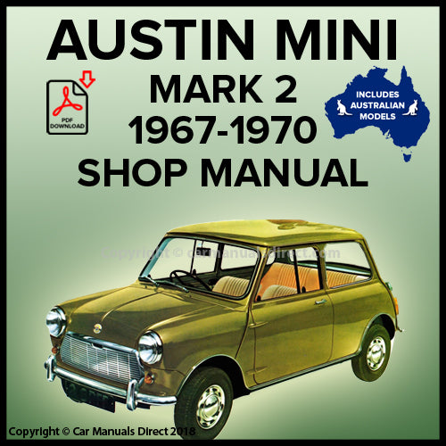
MORRIS MINI Mk 2 1967-70 Workshop Manual | PDF Download
MORRIS MINI Mark 2 1967-1970 Workshop Manual | PDF Download

This Mini Workshop Manual is for the following Mini models manufactured between 1967-1970:
-
Morris Mini
-
Morris Mini Super Deluxe
Engines:
- 848cc
- 998cc
- 1275cc
Below is a detailed list of topics covered in this Mini Workshop Manual:
- THE ENGINE
- Air cleaner
- Camshaft
- Carburetor
- Crankcase closed-circuit breathing
- Crankshaft and main bearings
- Cylinder head
- Decarbonizing
- Distributor spindle
- Engine and sub-frame
- Engine and transmission
- Engine mountings
- Exhaust manifold
- Exhaust pipe
- Flywheel and clutch
- Flywheel housing and primary gear
- Flywheel retaining screw thread
- Flywheel with diaphragm clutch
- Gear change remote control assembly
- Oil pressure
- Oil pressure relief valve
- Oil pump
- Pistons and connecting rods
- Primary gear oil seal replacement
- Rocker shaft
- Tappets
- Timing cover
- Timing gears and chain
- Transmission housing
- Valve timing
- Valves
- THE IGNITION SYSTEM
- Capacitor
- Distributor
- Sparking plugs
- Timing
- THE COOLING SYSTEM
- Fan belt
- Frost precautions
- Radiator
- Thermostat
- Water pump
- THE FUEL SYSTEM
- Air cleaner
- Carburetor
- Fuel pump:
- Type PD
- Type SP
- Testing
- Fuel tank
- Tank gauge unit
- THE CLUTCH
- Adjustments
- Overthrow
- Pedal movement
- Throw-out stop
- Master cylinder
- Overhaul (coil pressure spring type)
- Removal (diaphragm spring type)
- Slave cylinder
- THE TRANSMISSION
- Differential assembly
- Synchronizing cones
- Third motion shaft
- Three-speed synchromesh transmission
- Four-speed synchromesh transmission
- Transmission-dismantling and reassembling
- THE AUTOMATIC TRANSMISSION
- General description
- Power Flow diagrams (Mechanical)
- Line pressure and lubrication diagrams
- Adjustments
- Inhibitor switch
- Gear-change cable and selector rod
- Governor control rod
- Pressure check
- Stall speed check
- Auxiliary pump and governor
- Differential assembly
- Fault diagnosis
- First gear free-wheel assembly (one-way clutch)
- Forward clutch
- Gear-change cable
- Gear train
- Servo assembly
- Top and reverse clutch
- Transmission unit
- Valve block
- THE DRIVE SHAFTS
- General description
- Removing
- Servicing
- THE REAR SUSPENSION
- Hubs
- Hydrolastic suspension
- Depressurizing, evacuating, pressurizing
- Displacer units
- Radius arms
- Schrader valve extension housing
- Sub-frame
- Suspension pressures and wing heights
- Radius arms
- Spring units
- Sub-frame
- Sub-frame mountings
- THE STEERING
- Front wheel alignment
- Nylon tie-rod ball ends
- Steering-column
- Steering rack assembly
- Steering-rack lubrication
- Steering-wheel
- THE FRONT SUSPENSION
- Hydrolastic suspension
- Description
- Depressurizing, evacuating, pressurizing
- Displacer units
- Upper suspension arms
- Rubber suspension
- Lower arm
- Spring units
- Struts
- Upper arm
- Swivel hub ball joints
- Swivel hub outer oil seal
- Swivel hubs
- THE HYDRAULIC DAMPERS
- Priming
- Removal and refitting
- THE BRAKING SYSTEM
- Adjustment
- Bleeding
- Disc brake calliper
- Intensifier
- Master cylinder
- Pressure regulating valve
- Shoe assemblies (and disc friction pads)
- Wheel cylinders
- Two-leading-shoe front brakes
- Preventive maintenance
- THE ELECTRICAL SYSTEM
- Alternator (11AC)
- Control unit (4TR)
- Dismantling and overhauling
- Relay
- Service precautions
- Testing the charging circuit in position
- Warning light control
- Battery
- Bi-metal resistance instrumentation
- Cut-out
- Dynamo
- Lamps
- Starter
- Voltage regulator
- Windscreen wiper
- Wiring diagrams
- THE BODY
- Alignment
- Door locks
- Glasses
- Back-light
- Door
- Quarter-light
- Windscreen
- Heater assembly (recirculatory type)
- Heater assembly (fresh-air type)
- Instrument panel (Mk. I models)
- Roof liner
- Speedometer

File Format: PDF
Language: English
Print: Print the complete manual or just the pages you require
Bookmarked: Bookmarked for easy navigation
Requirements: We recommend using Adobe PDF Reader for best results
Device: We recommend downloading to a PC or Laptop or visit our Download Help Page for further information regarding Smart Devices
Images are Copyright©Car Manuals Direct and are used for promotional purposes only.
Copyright©Car Manuals Direct 2018

